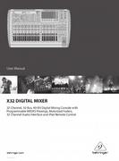
Behringer Music Mixer 32-Channel, 16-Bus, 40-Bit Digital Mixing Console with Programmable MIDAS Preamps, Motorized Faders, 32-Channel Audio Interface and iPad Remote Control User Manual
-

2.0
Owner's of the Behringer Music Mixer 32-Channel, 16-Bus, 40-Bit Digital Mixing Console with Programmable MIDAS Preamps, Motorized Faders, 32-Channel Audio Interface and iPad Remote Control gave it a score of 2.0 out of 5. Here's how the scores stacked up:
6 X32 DIGITAL MIXER Preliminary User Manual
–
5
5
0
–
10
10
–
20
–
30
–
40
–
50
–
60
–
00
–
5
5
0
–
10
10
–
20
–
30
–
40
–
50
–
60
–
00
–
5
5
0
–
10
10
–
20
–
30
–
40
–
50
–
60
–
00
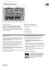
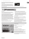
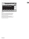
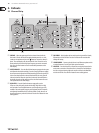
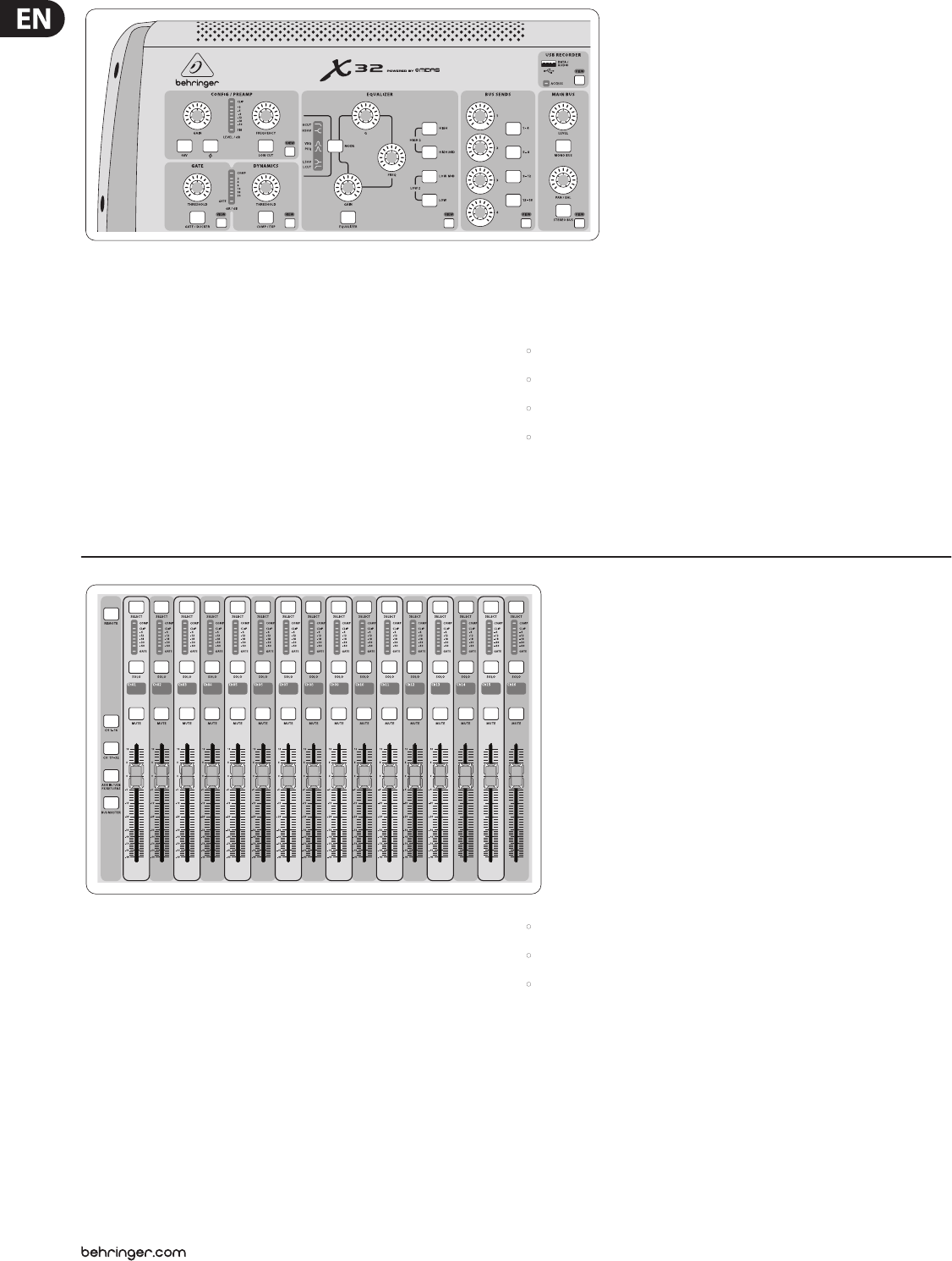
Input Channel Banks
You will nd a select button on top of every channel that is used to direct the
control focus of the user interface, including all channel related parameters
(channel strip and main display), tothat channel. Please note that at any time,
there is exactly onechannel selected (either Input Ch 1-32, Aux1-8, FXReturns
1L-4R, Mix Bus 1-16, Main LR/C, orMatrix 1-6). DCA Groups (digitally controlled
amplier) cannot be selected because they control a number of assigned
channels rather than one specic channel.
The Input Channels section of the console is locatedon the left hand side, and
oers 16 separate input channel strips. These 16 channel strips represent three
separate layers of inputs for the console, including:
• Input Channels 1-16
• Input Channels 17-32
• Auxiliary Inputs 1-6/USB playback/FX Returns 1L-4R
Press any of the correspondingly labeled layer buttons on the left side of the
console to switch the input channel bank to any of the three layers listed above.
The button will illuminate, reminding you which layer is active.
A fourth layer (Bus Masters) is also oered, allowingyou to adjust the levels of
the 16 Mix Bus Masters, which is useful when you wish to include Bus Masters
into DCA Group assignments.
VIEWVIEWVIEWVIEW
VIEW
VIEW
VIEW
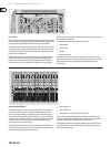
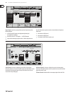
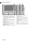
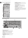
Channel Strip
The X32’s channel strip oers dedicated controls for the most important processing
parameters of the currently selected channel. To adjust controls for a given channel
strip, simply press the Select button on the desired input or outputchannel.
Certain sections of the channel strip (such as the low cut lter, noise gate, EQ and
compressor) contain a respectively labeled button that can be pressed to switch
the specic eect on and o. Thebutton illuminates to show the eect is active,
and goes dark when bypassed.
Within the channel strip, the rotary control knobs are surrounded by an amber
LED collar that indicates the parameter’s value. Whenever this backlit knob is
turned o, it indicates that this specic control/parameter is not available for
the selected channel type. For example, if an output bus is currently selected,
theLED collar and the gainknob are turned o, because there is no input gain to
be controlled on an output bus.
The channel strip consists of the following sub-sections:
• Cong/Preamp
• Gate, Dynamics
• Equalizer
• Bus Sends, Main Bus
Each of these subsections correspond to the processing steps of the currently
selected channel, and they each have their own View button that, when pressed,
switches the Main Display to a page displaying all related parameters for
thatsubsection.


Find Your Products By Category
Please Login
