Behringer Music Mixer 32-Channel, 16-Bus, 40-Bit Digital Mixing Console with Programmable MIDAS Preamps, Motorized Faders, 32-Channel Audio Interface and iPad Remote Control User Manual
-

2.0
Owner's of the Behringer Music Mixer 32-Channel, 16-Bus, 40-Bit Digital Mixing Console with Programmable MIDAS Preamps, Motorized Faders, 32-Channel Audio Interface and iPad Remote Control gave it a score of 2.0 out of 5. Here's how the scores stacked up:

47 X32 DIGITAL MIXER Preliminary User Manual
7.4 Routing Screen
The routing screen is where all signal patching is done, allowing you to route
internal signal paths to and from the physical input/output connectors located on
the console’s rear panel.
The routing screen contains the following separate tabs:
1. Home: Allows patching of physical inputs to the 32 input channels and
Auxinputs of the console.
2. Analog Out: Allows patching of internal signal paths to the console’s
16 rear-panel XLR outputs.
3. Aux Out: Allows patching of internal signal paths to the console’s
6 rear-panel ¼"/RCA auxiliary outputs.
4. P16 Out: Allows patching of internal signal paths to the 16 outputs of the
console’s 16-channel P16 Ultranet output.
5. Card Out: Allows patching of internal signal paths to the 32 outputs of the
XUF card.
6. AES50-A: Allows patching of internal signal paths to the 48 outputs of the
rear panel AES50-A output.
7. AES50-B: Allows patching of internal signal paths to the 48 outputs of the
rear panel AES50-B output.
None of the routing screen's tabs contains a secondary level of encoder functions.
When routing audio, the Layer up/down keys do not need to be used.
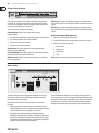
7.4.1 Routing Screen: Home Tab
The routing screen’s home tab allows the user to patch the console’s physical
rear-panel inputs to the 32 input channels and Aux inputs of the console.
As a default, the console maps the console’s 32 rear-panel analog inputs to their
the respective 32 channel inputs that are accessed on input fader layers one
and two, and maps the rear panel line-level (auxiliary) inputs to the third input
faderlayer.
However, the home tab of the routing screen can be used to change this
default assignment and “crosspatch” dierent physical inputs to dierent
channel inputs, in banks of 8 channels at a time. This allows the user to create a
custom layout of channel inputs that diers from the order that the sources are
plugged into the rear panel, and is easier than physically re-patching physical
audiocables.
To assign various inputs to the console’s input channels, perform the
followingsteps:
1. Adjust the rst rotary encoder to select which 8-channel audio input
source feeds input channels 1-8 of the console. As the encoder is rotated,
thecurrently selected input will be highlighted in the vertical list of choices.
2. When the desired 8-channel source is selected, push the 1st encoder to
“connect” the currently selected 8-channel source. The selected source now
feeds input channels 1-8 of the console.
3. Input choices that can be assigned include:
• Local 1-8
• Local 9-16
• Local 17-24
• Local 25-32
• AES50-A 1-8
• AES50-A 9-16
• AES50-A 17-24
• AES50-A 25-32
• AES50-A 33-40
• AES50-A 41-48
• AES50-B 1-8
• AES50-B 9-16
• AES50-B 17-24
• AES50-B 25-32
• AES50-B 33-40
• AES50-B 41-48
• Card 1-8
• Card 9-16
• Card 17-24
• Card 25-32
4. To assign an 8-channel source for the other input channels of the console
(9-16, 17-24, 25-32), simply repeat the process above, usingthe other four
rotary encoders on the same screen.
5. Choices for Aux In 1-4 include:
• Aux 1-4
• Local 1-4
• AES50-A 1-4
• AES50-B 1-4
• Card 1-4


Find Your Products By Category
Please Login
