Behringer Music Mixer 32-Channel, 16-Bus, 40-Bit Digital Mixing Console with Programmable MIDAS Preamps, Motorized Faders, 32-Channel Audio Interface and iPad Remote Control User Manual
-

2.0
Owner's of the Behringer Music Mixer 32-Channel, 16-Bus, 40-Bit Digital Mixing Console with Programmable MIDAS Preamps, Motorized Faders, 32-Channel Audio Interface and iPad Remote Control gave it a score of 2.0 out of 5. Here's how the scores stacked up:

43 X32 DIGITAL MIXER Preliminary User Manual
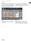
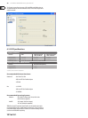
7.2.2 Home Screen: Cong Tab
The conguration tab allows selection of signal source/destination for the
channel, conguration of insert point, and other settings, as well as conguration
of the channel delay.
The cong tab contains the following parameters that can be adjusted using the
six rotary-push encoders:
1. Adjust the 1st encoder to control the input gain (trim) of the channel.
2. Tap the 1st encoder to allow linking of the channel with adjacent channel.
3. Adjust the 2nd encoder to set the low-cut frequency of the channel.
4. Tap the 2nd encoder to toggle the low-cut lter in/out of the signal path.
5. Adjust the 3rd encoder to scroll among all of the possible sources for
thechannel.
6. Tap the 3rd encoder to select the currently highlighted source and assign it
to the channel.
7. Adjust the 4th encoder to set the amount of digital line delay applied to
thechannel.
*Note – this is not an echo eect
8. Tap the 4th encoder to toggle the delay in/out of the signal path.
9. Adjust the 5th encoder to toggle the channel insert between pre and post
EQ/compressor.
10. Tap the 5th encoder to toggle the channel insert in/out of the signal path.
11. Adjust the 6th encoder to scroll among the signal path choices for the
insertpoint.
12. Tap the 6th encoder to assign the selected signal path to the insert point.
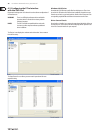
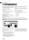
7.2.3 Home Screen: Gate Tab
The gate tab displays all aspects of the channel noise gate and allows for very
deep control of the gate eect. Whereas the top panel’s dedicated gate section
allows control of the gate’s threshold and in/out status, the gate tab oers many
more controls. This tab can also be accessed directly by pressing the “View”
button in the top panel Gate section.
The gate tab contains the following parameters, divided among two pages,
thatcan be adjusted using the six rotary-push encoders:
Page 1
1. Adjust the 1st encoder to set the input threshold of the gate.
2. Tap the 1st encoder to toggle the noise gate in/out of the signal path.
3. Adjust the 2nd encoder to set the range of a “ducking” eect applied to
thechannel.
4. Tap the 2nd encoder to toggle the ducker eect in/out of the signal path.
5. Adjust the 3rd encoder to set the attack time of the onset of the noise
gateeect.
6. Adjust the 4th encoder to set the hold time of the noise gate eect.
7. Adjust the 5th encoder to set the release time of the noise gate,
controllinghow quickly the gate opens up and lets the signal through.
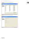
Page 2
1. Encoders 1 and 2 function the same on pages 1 and 2.
2. Adjust the 4th encoder to set the frequency of the key lter that can be used
to trigger the noise gate.
3. Tap the 4th encoder to toggle the key lter on/o, allowing a specic
frequency to control the gate.
4. Adjust the 5th encoder to set the steepness of the EQ slope used in the
keylter.
5. Tap the 5th encoder to send the key source to the solo bus, allowing the key
source to be monitored and evaluated.
6. Adjust the 6th encoder to select the specic key source to be used.
Choicesinclude “self” (the channel’s own signal) as well as any other
input/output of the console.
7. Tap the 6th encoder to assign the selected key source to the gate.


Find Your Products By Category
Please Login
